
SD SYSTEMS
- Versafloppy I
& II
The Western Digital
1771 LSI floppy disk controller chip revolutionized access to floppy disks. It handled
much of the disk IO hardware. SD Systems were one of the first companies to present
the chip on an S-100 board. Their "Versafloppy" was very reasonably priced and was
the first S-100 board to allow access to 5" and 8" drives from the same card. They
supplied source code for a simple diagnostic program and also supplied SDOS (their
version of CP/M) with the card.
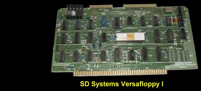
The card first appeared around 1978 . It represented a major
improvement over the discreet 7400 IC type chips then used on S-100 boards. The
1791 was a major factor in causing the drift away from the hard sector based Northstar
disc controller that up until then dominate the 5" floppy drive systems. It was
easier to program and lent itself nicely to writing a 128 byte soft sector BIOS
to work with CP/M. Shown above is the first version of the Versafloppy card
which became known as the Versafloppy-I. Most cards were purchased as kits and were
supplied with SDOS which was SD-Systems CPM configured to work with their Z80 CPU
card and monitor.
SD-Systems supplied a complete BIOS source code and small
diagnostic program with source code that allowed you to configure SDOS (CPM) for
your own system. One reason the Versafloppy caught on so quickly was that it offered
a relatively simple way for cassette based software users to tackle the "chicken
or egg" problem of being able to write a disk operation system BIOS before actually
having a disk operating system running to edit, assemble and store the files. At
that time IMSAI or Altair assumed you were talking to their hardware for their controller
board. With the SD Systems diagnostic Versafloppy program they supplied an option
to format, read and write disk sectors on any S-100 computer. You could load their
SDOS system into RAM, patch in links to your consol IO and get a basic system going
quickly. To this day, I still remember the feeling of great accomplishment I felt
the first time I saw my disk directory appear on my CRT with this board. It made
the hours of hardware building and debugging all worthwhile.
The Versafloppy I manual can be seen here
Versafloppy
I.pdf.
A major limitation of these systems, particularly the 5" drives,
was the total storage capacity of the drives was quite small. With the advent of
the Western Digital "double density" 1791 disk controller almost everybody moved
to double density drives. SD Systems quickly came out with their
Versafloppy II FDC
S-100 board. The same BIOS and diagnostic software was supplied allowing for an
easy upgrade in disk storage capacity. SD Systems continuously tweaked the
BIOS with upgraded versions allowing multiple disk formats for single and double
sided drives.
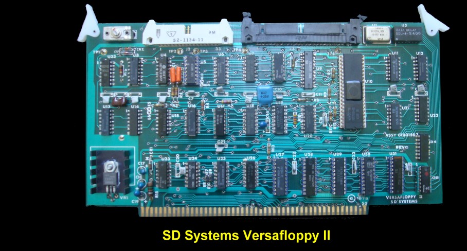
SD Systems put out two major versions of the Versafloppy
II board. They are shown above.
There are actually at least 3 versions of this disk controller card out there.
SD-Systems were one of the first companies to put our a disk controller S-100 card
that utilized the then new Western Digital 1791 LSI disk controller chip. The card
first appeared around 197x . It represented a major improvement over the discreet
7400 IC type chips then used on such boards. The 1791 was a major factor
in causing the drift away from the hard sector based Northstar disc controller that
up until then dominate the 5" floppy drives that started to appear at that time.
It was easier to program and lent itself nicely to writing a 128 byte soft sector
BIOS to work with CP/M. Figure 1 here is a picture of such a card. Most cards
were purchased as kits and were supplied with SDOS which was SD-Systems CPM configured
to work with their Z80 card and monitor. However SD-Systems supplied a complete
BIOS source code and small diagnostic program source code that allowed you to configure
SDOS (CPM) for your own system. One reason the Versafloppy caught on so quickly
was that it offered a relatively simple way for cassette based software users to
tackle the "chicken or egg" problem of being able to write a disk operation system
BIOS before actually having a disk operating system running to edit, assemble and
store the files. AT the time IMSAI or Altair assumed you were talking to their hardware
for their controller board. With the SD Systems diagnostic Versafloppy program they
supplied an option to format, read and write disk sectors. You could load their
SDOS system into RAM, patch in links to your consol IO and get a basic system going
quickly. To this day I still remember the feeling of great accomplishment I felt
the first time I saw my disk directory appear on my CRT. It made the hours of hardware
building and debugging all worthwhile.
The board was designed to work with the Western Digital 1791
or the later 1795 chips. I will discuss the differences below. From a hardware prospective
with this board they behave identical.
However two major versions of the Versafloppy II were made.
The differences had to do with how the data was obtained from the read write heads
of the disk. First take a look ate the Western Digital chip specs here. The 1791/5
chip requires a RAW READ Data (Pin 27) signal which is a 250 ns pulse per flux transition
and a Read clock (RCLK) signal to indicate flux transition spacing's. The RCLK (Pin
26) signal is provided by a Phase lock loop circuit on the board external to the
1791/5 chip. A Read Gate Signal (RG) is provided as an output (Pin 25) which can
be used to inform phase lock loops when to acquire synchronization. When reading
from the media in FM (single density). RG is made true when 2 bytes of zeroes are
detected. The FD179X must find an address mark within the next 10 bytes; otherwise
RG is reset and the search for 2 bytes of zeroes begins all over again. If an address
mark is found within 10 bytes, RG remains true as long as the FD179X is deriving
any useful information from the data stream. Similarly for MFM (double density),
RG is made active when 4 bytes of "00" or "FF" are detected. The FD179X must find
an address mark within the next 16 bytes, otherwise RG is reset and search resumes.
All this means that the reliability of the board depends on a good circuit to fish
out the raw data. On the early versions of the board (up to Rev. C) SD Systems used
a NE564 chip
for the phase look loop circuit. On later boards (Rev. P) they used a circuit involving
a LM301A OpAmp chip. The rest of the boards
appear to be identical.
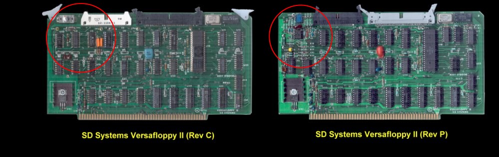
I have used both boards
and found no differences in terms or reliability or software.
One major issue with
all Versafloppy boards however is the fact that they were designed before the IEEE-696
specs came out. With older Z80 CPUs they work fine. With IEEE-696 systems there
is a slight problem. It has to do with the fact that the board utilizes the old
S-100 Clock 1 signal on pin 25 to clock in read and write data strobes to the 1791/5
chip. It counted on the fact that on older systems Clock 1 was an inverse of the
main bus clock (Clock 2, pin 24) and that the two did not overlap. With the IEEE-969
specks pin 24 is pSTVAL. It indicates when the status lines are valid but does not
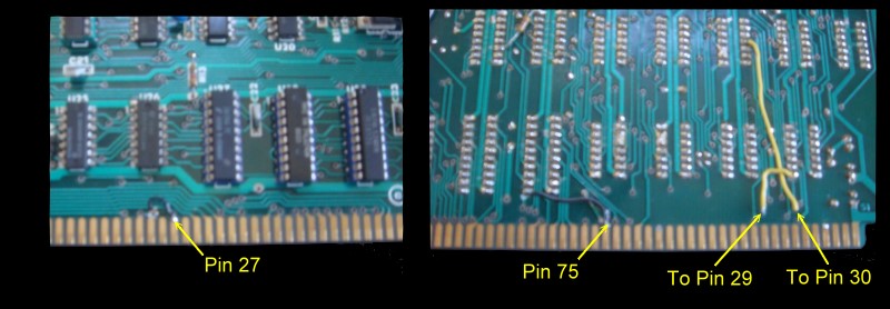
guarantee that it will not overlap with the master clock. The easiest solution
is to cut the trace from the bus going to pin 15 of U9 on the board and "piggy back"
a 74LS04 inverter IC on to the board. This is somewhat ugly but works fine. A better
solution is to use one of the IEEE-696 unused lines (I use S-100 pin 27) to
put on the bus an inverted signal from the master clock (pin 24). You can do this
from a prototype board anywhere on the bus or use a spare inverter on some other
board. This way you always have the "old" Clock 1 signal for older boards. You need
to cut the trace on the board from pin 27 going to pin 15 of U9 and redirect the
input of pin 15 of U9 it to the s-100 pin 27 as shown below.
Two other less important changes might also be considered.
The 1791/5 is initialized using the POC (S-100 pin 99) signal. In theory this should
be fine because if the chip "hangs" it should be cleared by sending it a software
RESET command (0D0H). However I found at times the board hung when I was experimenting
with device drivers etc. requiring a power down and power up to get a POC signal.
A better solution is to use the S-100 Reset signal (S-100 pin 75). Again a simple
trace cut and redirection of the input pin 11 of U27 does the trick. See the above
picture.
It does seem that towards the end SD Systems started to adders
this non IEEE-696 compliance problem. I have come across a schematic from them of
their Versafloppy II board as discussed above with the op-amp circuit as well as
a second schematic labeled "Versafloppy II-696". See the pdf files below. It not
clear to me if the IEEE-696 board was ever produced.
Finally for people that wish to move to 16 bit systems and
emulate the IBM-PC in their system there is a problem with the hard wired base port
SD Systems use with this board. The base port (from which all IO address to the
1791/5 go) is 60H. Unfortunately the IBM-PC utilizes ports 60H -6FH for the 8042
keyboard controller in the IBM-AT (or an 8255 in a PC). I use a Lomas S-100 Video
Board which emulates in hardware the IBM-PC video and keyboard hardware
and of course requires the 60H block of ports.
Fortunately it is easy to switch the
base port of the Versafloppy II to the 50H-57H block (unused on an IBM-PC). To do
this you must switch the A5 and A6 address lines coming to the board. On the standard
board address line A4 (S-100 pin 30), goes to pin 8 of U23 and address line
A5 (S-100 pin 29), goes to pin 4 of U16. cut the traces going to these chips and
switch over the signals. Two wires as shown above does the trick.
The Versafloppy II manual can be seen
here Versafloppy II.pdf
The Versafloppy II Schematic (for Rev C boards) can be
see
here
The Versafloppy II Schematic for
later boards can be seen
here.
The Versafloppy II - 697 Schematic can be seen
here
See
here for the Western Digital 1791/5 Data
sheets.
Versafloppy II Programming Considerations
SD Systems supplied a simple diagnostic
program to setup and test their original Versafloppy. They even went as far
as supplying a CPM "look -a-like" called SDOS that would run directly on their
SBC Z80
system. At the time most users were experiencing the chicken and egg problem
in that the software they needed to run CPM was supplied on a CPM disk but they
needed that software configured for their hardware setup. Things like Console I/O
etc. Fortunately the SD Systems diagnostic program which you could type in
by hand assemble and save via a Tarbell tape etc. allowed you to load any number
of sectors from a disk into memory. Since SD Systems supplied the source for their
BIOS you could easily patch in jumps for your hardware and bootstrap up a working
CP/M operating system. It was crude but it was a one time only event. From then
on all software was saved/read/exchanged of floppy disks. Other manufactures
tended to have BIOS and hardware hooks that were more difficult to figure out or
were undocumented. The Versafloppy caught on quickly.
The early drives were single density
-- indeed single sided drive systems. The almost universal format was the IBM 3740
8" 128 bytes/sector single sided disk format. While quite reliable and fast
when compared to cassette tapes such disks have very limited data storage capacity.
Typically about 270K.
Western Digital soon brought out a "double
density" chip which they called the 1791. Instead of FM signal encoding the chip
utilized a MFM encoding format thereby almost doubling the data density on a disk.
The gold standard again was an IBM format. One called the IBM System 34 format.
It utilized 256 byte sectors and allowed recording on both sides of the disk.
The 1791 was in fact a bit of a rush job. It really did not take care of double
sided disk recording. It was up to outside hardware to switch the recording heads
of the drives. They quickly corrected this by bringing out a second double density
chip called the 1795 which had a dedicated pin (pin 25) for disk side select.
Fortunately for us Versafloppy users
SD Systems did drive selection external to the Western Digital chips with
7400 chips on the board. The Versafloppy board hardware therefore will work
perfectly well with either a 1791 or a 1795 chip.
All this would be a mute point if it
were not for the fact that the sector read and write commands to a 1791 and 1795
chip are different. In order to understand this point it
might be useful to discuss how the 1791/1795 floppy disc controller is programmed.
1991/1795 Commands
The 1791/1795 chip contains five 8 bit registers
which completely control the chips functions. They are:-
Data Register.
This is the register to and from sector byte by byte data is obtained.
Track Register. The require disk track
is placed in this register. Upon a track seek the new track can be read from here
Sector Register. The require sector to be read/written
to is placed in this register.
Command Register This is the most important register it determines what next
the chip will do.
Status Register This register
contains various flag bits to describe command success or errors.
Tracks on a disk are laid down in the format:-
Track header...gap...(Track/Sector ID..gap..Data..gap) x N
times, ...End of Track
The Track/Sector ID consists of 6 bytes:-
Track#, Side (0 or 1), Sector#, Sector Size flag (,1,2,3
or 4) , and a 2 byte CRC check.
The command register accepts 11 different commands with very
precise bit patterns. They are summarized in this table.
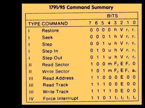
First you will notice that the commands
are grouped into 4 groups.
The Type I commands
control the head movement. Bits 0 and 1 determine
how fast the head will move from track to track. For most modern drives the maximum
speed so these bits are 0,0. The V bit determines if the chip will verify
if it is on the correct track after the head to track movement is complete. Normally
a 1 but for disk formatting it is set to 0. The h bit determines if the head is
to be lowered on to the disk before or after the command function is complete.
The
Type II commands
are clearly the most important (but the most complex).
Bit 0 of a Write sector 'a0' has to do with disk formatting and need not concern
us here.
F1 is another story. On a 1791 chip
this bit simply determines if the chip is to check if the active head is reading
from the requested side of the disk. If 0 the 1791 chip skips this side check. If
1 it checks that the active head is really on the requested side. The side of the
disk is contained in the Track/Sector ID field. The second byte of this field is
0 for side A (or a single sided disk). It is 1 for side B.
For the 1795 chip this bit actually
outputs on pin 25 a side select level. 0 for side A and a 1 for side B. As said
above the Versafloppy does not use this pin.
The E bit determines if there is to
be a slight time delay (15 ms) in setting the chip's busy flag after lowering the
head.
F2 on a 1791 chip is relevant if F1
was set to 1 (enable side compare). If it is 0 the sector side field must
also be 0 (Side A). If it is 1 then the sector side field must also be 1 (Side B).
F2 does something quite different on
a 1795 chip. It governs the meaning of the sector length field
in the above Track/Sector ID field. For a 128 byte sector on an IBM disk for example
the sector length flag is 0, a 256 byte sector it is 1, a 512 byte sector (MS-DOS)
it is 2 and a 1K byte sector it is a 3. This is how the old 1771 and
1791 chip interoperates the meaning of the byte in the field. IF
the F2 bit is a 1 the 1795 chip interoperates things the same way. If however it
is a 0 then the meaning of the length fields is switched around. A 0 means a 256
byte sector, a 1 means a 512 byte sector, a 2 means a 1K byte sector and a 3 means
a 128 byte sector. The data sheet from Western Digital says its to add on the fly
sector size flexibility!
What all this means is that a BIOS sector
read/write that works for a 1791 chip will nor work correctly for a 1795 chip and
vice versa. The differences are minor but enough to hang to system.
They are easily taken care of by using "ifdef's x1791 else x1795 endif's" in the
code. My Versafloppy diagnostic (VF.Z80) program illustrates this.
Finally the m bit allows you to read/write
contiguous sectors on a track. Very fast!
The
Type III command either reads the
above track/sector ID field or a whole track. The write track command is primarily
for disk formatting.
The
Type IV command, force interrupt command
is to pull the chip out of a lockup situation. It's basically a chip reset command.----To understand better how to control
the chip take a look here at a diagnostic program in Z80 code for the Versafloppy-II
recently I wrote called
VF.COM. Programming
this chip was a lot of fun and quite rewarding in allowing me to write a fast and
efficient CPM BIOS.
Rememberence: The 1791 chip was
designed and laid out by Pat Randleman -- well known in the indusrty. It was the
chip that really launched Westren Digital and got them into the Hard Disk drive
business. Sadly Pat passed away in October 25, 2009.
A Note On Old floppy Disks.
During the late 70's and early 80's I accumulated
well over 100 8" and 5" floppy disks with data. I stored them in the standard plastic
floppy cases of the time and generally stored them in dry cool places. Nothing special,
but no extreme exposure to heat etc. To my surprise and delight I was able to read
back the data without errors form almost all of them with the above Versafloppy
II some 30 years later. In one or two cases "rust" accumulated on the 8" floppy
head and had to be cleaned off. Even high density 1K byte sectored double density
CP/M 8" disks read fine. Not wishing to push my luck needless to say all data
is now on my Home Server properly backed up.
Other SD Systems S-100 Boards
8024 VDB
ExpandoRAM
ExpandoROM
SBC
VersaFloppy I & II
Z8800
PROM-100
I/O8 Serial Board 4KRAM
Other Boards
This page was last modified
on 01/08/2011